ColorBars / ColorBarsHD
The ColorBars and ColorBarsHD filters generate a video clip containing SMPTE color bars scaled to any image size. Both filters also generate audio, see the audio section for details.
ColorBars
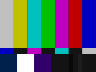
ColorBars produces a video clip containing SMPTE color bars (Rec. ITU-R BT.801-1) scaled to any image size. By default, a 640x480, RGB32, TV range, 29.97 fps, 1 hour long clip is produced.
Syntax and Parameters
ColorBars (int "width", int "height", string "pixel_type", bool "staticframes")
- width, height
Set size of the returned clip.
Default: 640, 480
- pixel_type
Set color format of the returned clip. May be any of the following: "RGB24", "RGB32", "RGB48", "RGB64", "YUY2", "YV12", "YV16" "YV24", "YV411", or any planar RGBPx, RGBAPx, YUV4xxPx, YUVA4xxPx format.
Default: "RGB32"
- staticframes
If set to false, generate all frames. Default true (one static frame is served).
Default: true
ColorBarsHD
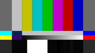
ColorBarsHD produces a video clip containing SMPTE color bars (Rec. ITU-R BT.709 / ARIB STD-B28 v1.0) scaled to any image size. By default, a 1288x720, YV24, TV range, 29.97 fps, 1 hour long clip is produced.
Syntax and Parameters
ColorBarsHD (int "width", int "height", string "pixel_type", bool "staticframes")
- width, height
Set size of the returned clip.
Default: 1288, 720
- pixel_type
Set color format of the returned clip. Must be "YV24" or any YUV444Px / YUVA444Px format.
Default: "YV24" (identical to "YUV444P8")
- staticframes
If set to false, generate all frames. Default true (one static frame is served).
Default: true
Audio
For both filters, an audio tone is also generated. The tone is a 440Hz sine at 48KHz sample rate, 32 bit (Float), stereo. The tone pulses in the right speaker, being turned on and off once every second. Level is 0 dBFS.
You can use Amplify to set a softer level (0dB can be a little deafening!)
ColorBarsHD
AmplifyDB(-20)
Broadcasting organizations usually specify an "alignment tone" accompanying colorbars at anywhere from -12 to -20 dBFS; if sending materials to another party, be sure to get their preferred alignment tone level. The exact level doesn't matter as long as all parties agree to it.
A note on notation
This page adopts the ITU style when discussing video levels which might be represented at different bit depths:
“ To avoid confusion between 8-bit and 10-bit representations, the eight most-significant bits are considered to be an integer part while the two additional bits, if present, are considered to be fractional part.
For example, the bit pattern
10010001would be expressed as 145d, whereas the pattern1001000101would be expressed as 145.25d. ”
Video levels shown below with the subscript "d" are assumed to be scaled by 2^(bit depth-8). For example, 235d at bit depth 10 becomes 235 × 2^(10-8) = 235 × 4 = 940.
see Deep Color
TV range
For both filters, in all color formats, luminance levels are TV (limited) range, where black=16d and white=235d, within a total possible range of 0-255d.
The table below shows the TV-range values ColorBarsHD generates, and those same values as they should be after converting to full range.
\(\mathtt{Y_\text{full} = (Y_\text{tv}-16_\text{d}) × 255_\text{d}/(235_\text{d}-16_\text{d})}\) // (for R, G, B, Y)
\(\mathtt{U_\text{full} = (U_\text{tv}-128_\text{d}) × 255_\text{d}/(240_\text{d}-16_\text{d}) + 128_\text{d}}\) // (for U, V)
\(\mathtt{Y_\text{tv} = Y_\text{full} × (235_\text{d}-16_\text{d})/255_\text{d} + 16_\text{d}} \quad\) // (for R, G, B, Y)
\(\mathtt{U_\text{tv} = (U_\text{full}-128_\text{d}) × (240_\text{d}-16_\text{d})/255_\text{d} + 128_\text{d}}\) // (for U, V)
Color bar |
TV range output |
(expanded to full range) |
|||||||||||||
|---|---|---|---|---|---|---|---|---|---|---|---|---|---|---|---|
R |
G |
B |
Y |
U |
V |
R |
G |
B |
Y |
U |
V |
||||
75% White |
180d |
180d |
180d |
180d |
128d |
128d |
191d |
191d |
191d |
191d |
128d |
128d |
|||
75% Yellow |
180d |
180d |
16d |
168d |
44d |
136d |
191d |
191d |
0d |
177d |
32d |
137d |
|||
75% Cyan |
16d |
180d |
180d |
145d |
147d |
44d |
0d |
191d |
191d |
150d |
149d |
32d |
|||
75% Green |
16d |
180d |
16d |
133d |
63d |
52d |
0d |
191d |
0d |
136d |
54d |
41d |
|||
75% Magenta |
180d |
16d |
180d |
63d |
193d |
204d |
191d |
0d |
191d |
55d |
201d |
214d |
|||
75% Red |
180d |
16d |
16d |
51d |
109d |
212d |
191d |
0d |
0d |
41d |
106d |
223d |
|||
75% Blue |
16d |
16d |
180d |
28d |
212d |
120d |
0d |
0d |
191d |
14d |
223d |
118d |
|||
These colors are at "75%" of maximum, per common broadcast practice. You may occasionally see "100%" color bars.[1] They are rather useless, as you cannot detect gain or saturation that is too high on a signal that is already at maximum.
PLUGE
The lower part of the frame is called the PLUGE (also lowercase: "pluge") signal. From left to right it consists of: -I, white, +Q, then a series of black and near-black bars: 0, -4, 0, +4 and 0 IRE relative to black.
Note 'IRE' is used here to mean 'percent luminance', on a scale from 0 (black) to 100 (white), ignoring the varying broadcast standards where black might be 0 IRE or 7.5 IRE depending on the country.
This section documents the ColorBars pluge only; ColorBarsHD's pluge is similar, but dispenses with -I and +Q.
The table below show the TV-range values ColorBars generates, and those same values as they should be after converting to full range.
PLUGE Element |
TV range output |
(expanded to full range) |
|||||||||||||
|---|---|---|---|---|---|---|---|---|---|---|---|---|---|---|---|
R |
G |
B |
Y |
U |
V |
R |
G |
B |
Y |
U |
V |
||||
-I |
0d |
58d |
98d |
16d |
158d |
95d |
-19d |
49d |
95d |
0d |
162d |
90d |
|||
100% White |
235d |
235d |
235d |
235d |
128d |
128d |
255d |
255d |
255d |
255d |
128d |
128d |
|||
+Q |
59d |
15d |
126d |
16d |
174d |
149d |
50d |
-1d |
128d |
0d |
180d |
151d |
|||
Black |
16d |
16d |
16d |
16d |
128d |
128d |
0d |
0d |
0d |
0d |
128d |
128d |
|||
-4 IRE |
7d |
7d |
7d |
7d |
128d |
128d |
-10d |
-10d |
-10d |
-10d |
128d |
128d |
|||
Black |
16d |
16d |
16d |
16d |
128d |
128d |
0d |
0d |
0d |
0d |
128d |
128d |
|||
+4 IRE |
25d |
25d |
25d |
25d |
128d |
128d |
10d |
10d |
10d |
10d |
128d |
128d |
|||
Black |
16d |
16d |
16d |
16d |
128d |
128d |
0d |
0d |
0d |
0d |
128d |
128d |
|||
(negative values will be clipped to 0) |
|||||||||||||||
The -I and +Q bars are vestigial artifacts of NTSC analog TV and are not really used any more.
The -4, 0 and +4 IRE bars can be used to set your monitor brightness – assuming your playback chain expands TV range (16d-235d) to full-range (0-255d) as shown in the images above. The -4 IRE and 0 IRE bars should have the same apparent brightness (they should be as dark as the monitor can display), and the +4 should be a little brighter. If you can see the -4 bar, your monitor brightness is set too high; if you cannot see the +4 bar, your monitor brightness is set too low.[2]
Note, the pluge signal goes out of 16-235d range in the -I and the -4 bars. These cannot be accurately converted to 0-255d range.
More information about the colorbars and the PLUGE can be found on the color bars theory page.
Miscellaneous
Note, that for example
ColorBars(pixel_type="YUV444P8")
...is equivalent to
ColorBars(pixel_type="RGB32")
ConvertToYUV444(matrix="PC.601")
# "PC.601" / "PC.709" / "PC.2020" don't scale the luma range
When directly generating YUV format data, the color transitions are arranged to occur on a chroma-aligned boundary.
Changelog
Version |
Changes |
|---|---|
AvsiSynth+ 3.4.0 |
ColorBars: add support for all YUV(A)422 formats and
RGB24, RGB48, YV411.
|
AvsiSynth+ r2487 |
ColorBars: add support for all YUV(A)444/420, planar
RGB(A) formats and RGB64.
ColorBarsHD: add support for all YUV(A)444 formats.
|
AviSynth 2.6.0 |
Added pixel_type="YV24" to ColorBars.
Initial release of ColorBarsHD.
|
AviSynth 2.5.6 |
Added
pixel_type parameter.Added "YUY2" and "YV12" pixel types.
|
AviSynth 2.5.5 |
Width and height parameters are now named and optional. |
$Date: 2022/04/17 03:58:18 $
